Understanding Compute Express Link (CXL) and Its Alignment with the PCIe Specifications
- Steve Scargall
- Cxl
- May 7, 2024
How CXL Uses PCIe Electricals and Transport Layers
CXL utilizes the PCIe infrastructure, starting with the PCIe 5.0. This ensures compatibility with existing systems while introducing new features for device connectivity and memory coherency. CXL’s ability to maintain memory coherency across shared memory pools is a significant advancement, allowing for efficient resource sharing and operand movement between accelerators and target devices.
CXL builds upon the familiar foundation of PCIe, utilizing the same physical interfaces, transport layer, and electrical signaling. This shared foundation makes CXL integration with existing PCIe systems seamless. Here’s a breakdown of how it works:
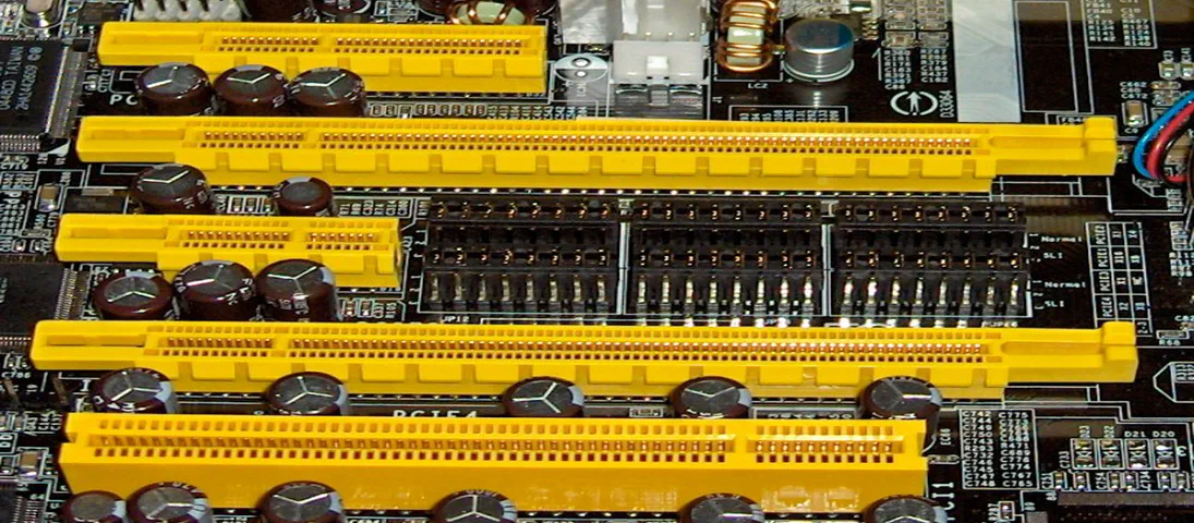
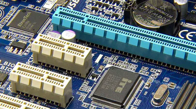
Physical and Electrical Interface: CXL devices utilize the same physical slots and electrical connectors as PCIe devices. This eliminates the need for completely new hardware designs, simplifying adoption.
Transport Layer: Similar to PCIe, CXL employs the PCI Express packet and flit (flow control unit) structure for data transfer. This ensures compatibility with existing PCIe controllers and switches.
However, CXL goes beyond simply replicating PCIe. It introduces its own set of protocols on top of the PCIe infrastructure to cater to the specific needs of high-performance accelerators and attached devices:
CXL.io: This protocol handles device I/O communication. It builds upon the PCIe I/O protocol but offers features like relaxed ordering and credit-based flow control, optimizing data transfers for accelerators.
CXL.mem: This protocol enables coherent memory access between the host processor and CXL devices. It provides a shared memory space, allowing the processor to directly access memory on the accelerator, reducing data movement overhead.
CXL.cache: This protocol facilitates cache coherency between the host processor cache and the cache hierarchy of CXL devices. This ensures data consistency and avoids unnecessary cache invalidations, improving overall system performance.
By combining the established foundation of PCIe with its own innovative protocols, CXL delivers a high-bandwidth, low-latency interconnect specifically designed for the demands of modern accelerators and data centers.
PCIe Bandwidths and Corresponding CXL Specifications
Tabel 1 below presents a comparison of the theoretical maximum bandwidths for various generations of PCI Express (PCIe) and their corresponding Compute Express Link (CXL) specifications. The bandwidth values are bi-directional, meaning they represent the combined rate of data transfer in both directions (from and to the device). It’s important to note that these figures are theoretical maximums and actual performance may vary based on system design and other factors.
| PCIe Generation | CXL Specification | x1 Lanes | x2 Lanes | x4 Lanes | x8 Lanes | x16 Lanes |
|---|---|---|---|---|---|---|
| 2.5 GT/s (PCIe 1.x) | - | 500 MB/s | 1 GB/s | 2 GB/s | 4 GB/s | 8 GB/s |
| 5.0 GT/s (PCIe 2.x) | - | 1 GB/s | 2 GB/s | 4 GB/s | 8 GB/s | 16 GB/s |
| 8.0 GT/s (PCIe 3.x) | - | 2 GB/s | 4 GB/s | 8 GB/s | 16 GB/s | 32 GB/s |
| 16.0 GT/s (PCIe 4.x) | - | 4 GB/s | 8 GB/s | 16 GB/s | 32 GB/s | 64 GB/s |
| 32.0 GT/s (PCIe 5.x) | 1.0, 1.1, 2.0 | 8 GB/s | 16 GB/s | 32 GB/s | 64 GB/s | 128 GB/s |
| 64.0 GT/s (PCIe 6.x) | 3.0, 3.1 | 16 GB/s | 32 GB/s | 64 GB/s | 128 GB/s | 256GB/s |
| 128.0 GT/s (PCIe 7.x) | TBD | 32 GB/s | 64 GB/s | 128 GB/s | 256GB/s | 512GB/s |
Table 1: Bi-Directional PCIe and CXL Bandwidth Comparison. Encoding overhead and header efficiency is not included.
Reference: PCIe 7.0 Speeds and Feeds
For example, the “x16 Lanes” column indicates the bandwidth available on a 16-lane (x16) PCIe connection. At the PCIe 1.x generation’s transfer rate of 2.5 GT/s (gigatransfers per second), the x16 configuration can theoretically support up to 8 GB/s of data flowing in each direction simultaneously.
As we progress through the generations, the bandwidth doubles with each iteration, reflecting advancements in technology that allow for faster data transfer rates. The CXL specifications listed align with the PCIe generations that introduced comparable bandwidth capabilities, ensuring that devices using CXL can take full advantage of the speeds offered by the corresponding PCIe generation.
Understanding Gigatransfers per second (GT/s)
PCIe uses gigatransfers per second (GT/s) as a unit to specify its raw data transfer rate. It’s important to understand the distinction between GT/s and the more common gigabits per second (Gbps) because PCIe employs data encoding to ensure reliable data transmission.
Unlike memory interfaces that often use simple binary data streams, PCIe is a serial bus. This means it transmits data one bit at a time. Additionally, the clock signal that synchronizes data transfer is embedded within the data stream itself.
To ensure the receiver can recover the clock signal from the data stream, there needs to be enough transitions between high (1) and low (0) voltage levels. Simply sending a long string of 1s or 0s wouldn’t provide enough transitions for the receiver to accurately determine the clock.
To address this challenge, PCIe utilizes data encoding schemes:
- PCIe Gen 1 and Gen 2 use 8b/10b encoding, where 8 bits of data are encoded into a 10-bit symbol. The extra 2 bits serve as control characters, ensuring DC balance and providing error detection capabilities. However, this encoding introduces a 25% overhead (2 extra bits for every 8 bits of data).
- PCIe Gen 3 and later use 128b/130b encoding improves upon 8b/10b by reducing overhead, which further improves efficiency. It uses 128-bit blocks, with 2 bits reserved for the block header (preamble) and 130 bits for data. The payload data rate of 128b/130b is identical to 64b/66b, but it achieves this with less overhead. By using longer blocks and efficient encoding, 128b/130b minimizes the number of extra bits needed for control and synchronization.
The GT/s value represents the number of these encoded symbols transferred per second on a single lane.
Converting GT/s to Gbps and GB/s
Since the encoding adds overhead bits, the actual data payload transferred is less than the raw transfer rate. To calculate the actual data throughput in Gigabits per second (Gbps), we need to consider the specific encoding scheme used by the PCIe generation. For example:
To convert GT/s to GB/s, we need to consider the effective data rate after encoding. For PCIe Gen 3 (128b/130b encoding), the effective data rate is approximately 98.46% of the raw data rate. Therefore, the actual data payload transferred per lane is (8 GT/s) * (128 bits/symbol) / (130 bits/symbol) which is approximately 7.88 Gbps.
To convert Gbps to GB/s, we multiply the effective data rate by 8 (since 1 byte = 8 bits):
- GB/s = (Effective data rate in Gbit/s) / 8
Example: If a system operates at 8 GT/s (Gen 3):
Gbps = ((8 x 1,000,000,000) * 128) / 130) = (7876923076 bits per second / 1,000,000,000) == 7.88 GBit/s GB/s = 7.88 Gbit/s / 8 = 0.985 per PCIe Lane one-way (uni-directional)
Table 1 shows the bi-directional theoretical throughput, not including the encoding or header overhead, so we multiply 0.985 GB/s x 2 to get 1.97 GB/s, which matches the x1 value in Table 1.
Hopefully, this helps you to perform your own calculations for the other table cells.
Summary
In summary, GT/s represents the raw data transfer rate, while GB/s accounts for the effective payload data rate after encoding. Understanding this distinction is crucial when designing and optimizing high-speed communication systems.
These values may vary based on specific technologies and encoding methods, but this explanation provides a general understanding of GT/s and its conversion to GB/s.

